Ever wonder why some devices fail prematurely while others thrive under heavy workloads? The answer often lies in thermal management—specifically, the role of components designed to dissipate excess energy. At the core of this process are heat sinks, passive devices that transfer unwanted warmth away from sensitive electronics. Without them, circuits risk overheating, leading to reduced efficiency or catastrophic failure.
Selecting the right solution isn’t just about picking a metal block. It requires understanding thermal impedance, operating conditions, and the unique demands of your application. Whether you’re working with BJTs, MOSFETs, or advanced processors, each scenario demands precise calculations to balance temperature, power output, and physical constraints.
This guide breaks down the science behind effective heat dissipation. You’ll learn how to evaluate your system’s needs, from basic airflow considerations to advanced material properties. We’ll explore why a one-size-fits-all approach fails and how to avoid common pitfalls in electronic design.
By the end, you’ll have actionable strategies to optimize performance and longevity. Let’s dive into the principles that separate adequate thermal control from truly robust solutions.
Understanding Thermal Management Fundamentals
Effective thermal management starts with mastering core scientific principles. Every electronic system relies on precise balance between heat generated and dissipation capacity. Ignoring this equilibrium risks component failure, energy waste, and costly redesigns.
Key Terminology in Thermal Performance
Thermal conductivity measures a material’s ability to transfer heat. Metals like aluminum (200-250 W/mK) excel here, while plastics often fall below 1 W/mK. Thermal resistance, expressed in °C/W, quantifies how much a component impedes heat flow from source to environment.
Consider junction-to-case resistance: a MOSFET’s silicon die might reach 1.5°C/W to its casing. Junction-to-ambient values account for entire thermal paths, including heatsinks. Lower resistance means better cooling potential.
Importance of Effective Heat Dissipation
High power dissipation directly raises operating temperature. A 100W CPU with 0.5°C/W thermal resistance hits 50°C above ambient. In confined spaces, this can trigger thermal runaway—exponential temperature spikes that destroy circuits.
Optimizing surface area accelerates heat transfer. Finned designs increase exposure to air or liquid coolants. Forced convection systems in servers demonstrate this principle, maintaining safe temperature thresholds even under 40°C ambient conditions.
Components Affecting Heat Sink Performance
Thermal control systems rely on precise combinations of materials and geometries to achieve optimal results. Two elements dominate this equation: the base material and the structural design. Both factors directly influence how efficiently energy moves away from sensitive components.
Heat Sink Materials and Their Conductivity
Aluminum and copper dominate thermal management applications. Aluminum alloys offer 200-250 W/mK conductivity at 60% lower weight than copper. Copper reaches 400 W/mK but costs 3x more. Hybrid designs often use copper bases with aluminum fins to balance performance and cost.
| Material | Conductivity (W/mK) | Weight | Typical Use |
|---|---|---|---|
| Aluminum 6063 | 210 | 2.7 g/cm³ | Consumer electronics |
| Copper C110 | 390 | 8.9 g/cm³ | High-power servers |
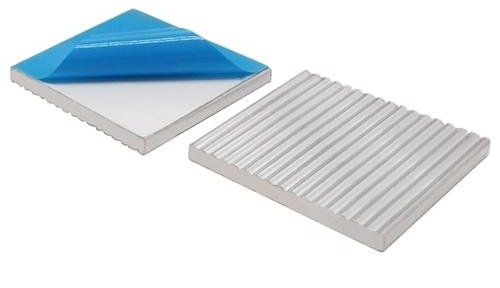
Fin and Pin Designs for Increased Surface Area
Extended surfaces amplify cooling capacity. Straight fins provide 40% more exposure than flat plates in forced-air systems. Pin-fin arrays improve turbulence in compact spaces, boosting heat transfer by 15-25% compared to traditional designs.
LED arrays often use radial fin configurations to maximize natural convection. Power converters employ staggered pins to handle 500W+ loads. Proper geometry selection can reduce junction temperatures by 20°C in critical applications.
Designing a Thermal Path: Calculations and Considerations
Thermal path optimization starts with three critical resistance values. Junction-to-case, case-to-sink, and sink-to-ambient resistances form a chain determining total thermal impedance. Each link must be minimized to prevent dangerous temperature rise.
Power Dissipation and Thermal Impedance Calculations
Calculate maximum power dissipated using component datasheets. Multiply this value by total thermal resistance to predict temperature increase. For example:
| Component | Thermal Resistance (°C/W) | Impact |
|---|---|---|
| Junction-to-case | 1.2 | Internal heat flow |
| Case-to-sink | 0.5 | Interface efficiency |
| Sink-to-ambient | 3.0 | Cooling system performance |
A 50W device with 4.7°C/W total resistance reaches 235°C above ambient. This exceeds most component limits, demanding better cooling. Heat sink calculator tools automate these calculations, factoring in ambient air conditions.
Assessing Ambient and Operating Temperature Limits
Natural convection systems work in open environments below 35°C. Forced airflow reduces effective resistance by 40-60% in enclosed spaces. Always verify maximum junction temperatures against calculated values.
Industrial controllers in 50°C environments need different solutions than consumer devices. Consider seasonal ambient air variations and altitude effects on cooling capacity.
How to choose a heat sink
Engineers face critical decisions when matching cooling components to system demands. The right solution depends on precise alignment between thermal requirements and physical constraints. Three primary factors dominate this process: operational parameters, environmental conditions, and performance trade-offs.
Selection Criteria for Varying Applications
Different applications impose unique thermal challenges. Industrial controllers in dusty warehouses require rugged sinks with sealed fin designs. Medical devices prioritize compact profiles that fit sterilized environments. Always evaluate maximum power loads, spatial limitations, and exposure to contaminants.
Outdoor equipment demands corrosion-resistant materials like anodized aluminum. High-altitude installations need larger surface areas due to thinner air. Automotive systems require vibration-resistant mounting solutions. Each scenario demands tailored selection strategies.
Utilizing Heat Sink Calculators and Vendor Specifications
Modern thermal management leverages digital precision. Leading manufacturers provide heat sink calculator tools that analyze junction temperatures, airflow rates, and ambient conditions. These platforms output optimized dimensions and material recommendations within seconds.
Always cross-reference vendor datasheets for verified thermal resistance values. Key specifications include base thickness, fin density, and maximum derating curves. Balance cost against performance—copper bases boost conductivity but increase weight by 230% versus aluminum.
Proper sizing prevents two critical errors: oversized units wasting space and resources, undersized models risking thermal runaway. A comprehensive evaluation of all parameters ensures reliable operation across the device’s lifespan.
Enhancing Thermal Performance: Tips and Best Practices
Advanced cooling systems separate reliable electronics from those prone to failure. Optimizing thermal performance requires strategic material selection and intelligent design adaptations. Three critical factors determine success: interface efficiency, airflow methods, and geometric innovation.
Thermal Interface Materials: Bridging the Gap
Thermal interface materials eliminate air pockets between components and cooling surfaces. Silicone-based pastes reduce case-to-sink resistance by 35% compared to dry contacts. Phase-change compounds maintain consistent pressure under vibration, crucial for automotive systems.
| Material Type | Conductivity (W/mK) | Application |
|---|---|---|
| Thermal Paste | 3-8 | Consumer CPUs |
| Graphite Pads | 5-15 | Industrial Controllers |
| Liquid Metal | 73 | High-performance GPUs |
Airflow Strategies: Passive vs Active Cooling
Natural convection suits low-power devices in open environments. Forced airflow doubles heat transfer rates in confined spaces. Server farms use centrifugal fans to maintain 2.5m/s airflow across fin arrays.
Surface Area Maximization Techniques
Staggered pin configurations increase surface area heat dissipation by 18% versus straight fins. Extruded aluminum profiles with micro-grooves boost contact points by 40%. A telecom case study showed 22°C reductions using corrugated fin designs.
Key design principles for management success:
- Match fin density to airflow capabilities
- Use anodized coatings in corrosive conditions
- Test prototypes under seasonal temperature extremes
Conclusion
Proper thermal control remains the backbone of reliable electronics. Effective thermal management prevents catastrophic failures by maintaining operating temperature thresholds. Calculations using power dissipated values and thermal resistance formulas ensure components stay within safe limits.
Material selection directly impacts performance. Aluminum balances cost and conductivity, while copper excels in high-power scenarios. Design enhancements like pin-fin arrays boost dissipation by 25% in constrained spaces.
Always match application needs to sink specifications. Rugged environments demand corrosion-resistant coatings, while compact electronic devices require optimized fin density. Tools like heat sink calculators simplify these decisions using ambient temperature data and airflow metrics.
Final recommendations: Test prototypes under real conditions, verify vendor thermal ratings, and prioritize adaptive designs. These steps guarantee systems operate efficiently across their lifespan without thermal throttling or damage.