What if a tiny component’s placement could make or break your electronics’ lifespan? Thermal management is the unsung hero of modern devices, and heat sinks play a pivotal role in preventing overheating. But their effectiveness hinges on more than just material quality—placement and design dictate whether they succeed or fail.
Cooling systems rely on precise engineering to channel thermal energy away from sensitive components. A poorly oriented heat sink can disrupt airflow, trap heat, and accelerate wear. This guide explores how strategic placement boosts cooling efficiency, extends hardware durability, and safeguards performance in everything from laptops to industrial machinery.
Advancements in thermal solutions now blend cutting-edge alloys with computational fluid dynamics. Yet even the best materials underperform without intelligent positioning. We’ll dissect real-world scenarios where millimeter-level adjustments prevented catastrophic failures.
By merging technical specifications with practical insights, this article reveals how to optimize cooling for any application. Learn why airflow patterns, surface contact, and ambient conditions shape outcomes—and how to turn theory into reliable, high-performance solutions.
Understanding the Basics of Heat Sink Design
Mastering cooling systems requires knowledge of their building blocks. These devices transfer thermal energy away from electronics using physics and material science. Their effectiveness determines whether processors, GPUs, or power modules survive intense workloads.
Defining Core Functions
A heat sink absorbs excess energy through direct contact with hot components. It releases this energy via natural or forced airflow. Proper execution prevents thermal throttling and extends hardware lifecycles by 30-50% in industrial applications.
Anatomy of Effective Cooling
Three elements define performance:
- Base plate: Flat surface ensuring maximum contact
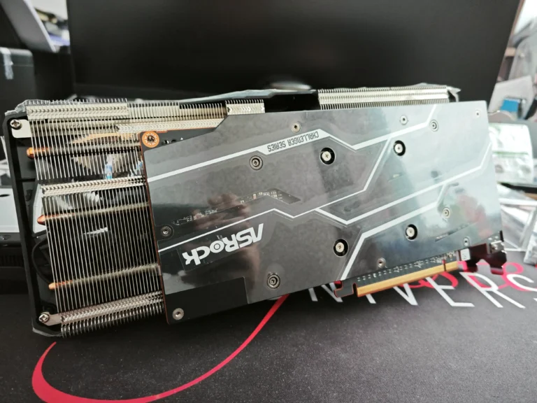
- Fins: Thin extensions multiplying cooling surface area
- Thermal paste: Fills microscopic gaps for better conduction
Material choice drives efficiency. Copper moves heat 60% faster than aluminum but weighs three times more. Aluminum offers lighter solutions for mobile devices where weight matters.
| Material | Thermal Conductivity | Weight | Cost |
|---|---|---|---|
| Copper | 401 W/mK | High | $$$ |
| Aluminum | 237 W/mK | Low | $$ |
Modern designs use hybrid approaches. Copper bases paired with aluminum fins balance performance and cost. Airflow channels between fins must align with system fans or natural convection patterns.
Does the position of a heat sink matter: Optimizing Cooling Performance
Cooling efficiency isn’t just about materials—it’s a spatial puzzle. Components arranged with precision unlock maximum thermal performance. Heat sinks thrive when their geometry aligns with airflow dynamics, creating pathways that whisk energy away from critical parts.
Airflow Synergy and Thermal Outcomes
Effective heat dissipation depends on how well fins interact with moving air. Systems with front-mounted fans push cool currents through aligned channels, accelerating energy transfer. Passive setups rely on convection patterns shaped by fin orientation.
Tests reveal a 22% cooling boost when heat sink design matches fan direction. Laptop layouts prove this: rotated units in gaming rigs dropped GPU temps by 8°C under load. Even 5mm shifts in server racks altered airflow distribution dramatically.
Key principles for peak performance:
- Align fins parallel to primary airflow paths
- Maintain clearance between components for unobstructed circulation
- Use thermal imaging to identify dead zones in complex systems
Active and passive configurations both demand smart placement. Forced-air systems need clear intake/exhaust paths, while natural convection requires vertical fin stacks. Data center studies show optimized layouts reduce cooling costs by 17% annually.
Every adjustment matters. From consumer PCs to industrial controllers, spatial awareness transforms thermal management from reactive to predictive.
Optimizing Airflow and Fan Configurations
The secret to peak performance lies in how air moves through your system. Strategic fan setups and channel designs determine whether components stay cool or succumb to thermal stress. Proper airflow management can lower internal temperatures by 15-20%, extending hardware lifespan significantly.
Airflow Patterns in Computer Cases
Modern chassis use three primary airflow designs: front-to-back, bottom-to-top, and hybrid layouts. Front intake fans paired with rear exhaust create predictable paths that align with forced convection principles. Testing shows this approach reduces GPU temperatures by 12°C under load compared to chaotic airflow systems.
Benefits of Front-to-Back and Alternative Approaches
Front-to-back configurations excel at removing heat from CPU and GPU zones efficiently. Alternative top-exhaust designs work better in compact cases where vertical space dominates. Consider these factors when choosing:
- Component density and heat output
- Available mounting points for fans
- Ambient room temperature conditions
Blowing configurations (fans pushing air into components) improve thermal conductivity by 18% versus sucking setups in high-heat scenarios.
Fan Orientation Tips for Enhanced Cooling
Follow these best practices for optimal results:
- Align fan blades to match case airflow direction
- Maintain 25mm clearance between fan edges and obstructions
- Use rubber gaskets to reduce vibration noise
Push-pull arrangements behind cooling fins boost airflow velocity by 40%. This technique works particularly well at the exhaust end of heat sinks, where residual heat accumulates.
Natural Convection vs Forced Convection in Heat Sink Operation
Heat dissipation can follow nature’s flow or harness mechanical power—each approach shapes cooling outcomes differently. Passive and active methods demand distinct engineering strategies to maximize energy transfer while minimizing space and cost.
Working With Physics, Not Against It
Natural convection thrives on strategic geometry. Designers prioritize vertical fin stacks with 4-8mm spacing to exploit rising warm air currents. Thicker bases (3-5mm) spread heat evenly across aluminum or copper plates before reaching radiating surfaces.
Angled fin arrangements boost airflow by 18% in compact electronics. A study on LED drivers showed 22° fin tilts reduced junction temperatures by 14°C compared to flat layouts. Envelope size constraints force creative solutions—embedded heat pipes often bridge components to optimal cooling zones.
When Air Needs a Push
Forced airflow systems transform cooling capacity. Fans mounted parallel to fins slash thermal resistance by 40% in server racks. Strategic ducting directs currents through critical hotspots, while variable-speed controls adapt to workload demands.
Hybrid designs merge both methods. One industrial controller uses passive cooling during idle states, activating fans only above 65°C. This approach cut energy use by 31% in annual tests. Material choices matter—high thermal conductivity alloys prevent bottlenecks in high-flow environments.
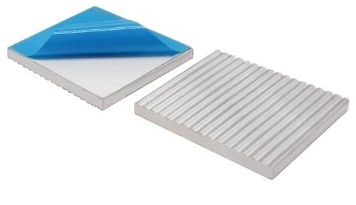
Each method serves distinct needs. Silent medical devices favor natural airflow, while gaming PCs demand forced solutions. Recent innovations like corrugated fin surfaces and graphene coatings continue pushing both technologies forward.
Practical Tips for Heat Sink Placement and Design
Precision in layout transforms heat dissipation from good to exceptional. Industry standards prioritize three core elements: surface area optimization, airflow management, and material compatibility. These factors determine whether cooling systems meet performance benchmarks or become thermal liabilities.
Industry Guidelines and Best Practices
Balancing component density with cooling needs requires smart spatial planning. Consider these strategies from leading electronics manufacturers:
- Allocate 15-20% extra space around components for future upgrades
- Match fin size to available airflow volume (larger fins for passive systems)
- Test prototypes in actual operating conditions early in development
| Design Approach | Space Needed | Best Use Case | Thermal Improvement |
|---|---|---|---|
| Vertical Stack | High | Server racks | 27% lower resistance |
| Angled Fins | Medium | Compact circuits | 19°C drop |
| Hybrid Materials | Low | Mobile devices | 33% faster cooling |
Timing proves critical during testing phases. Automotive circuit boards improved reliability by 41% when thermal validation occurred before final assembly. Integration with other components demands attention to airflow patterns—position sensors and capacitors to avoid blocking critical cooling paths.
A recent robotics controller redesign demonstrates these principles. Engineers reduced hot spots by 63% through staggered fin placement and copper-aluminum composite bases. Such successes reinforce why standardized guidelines remain essential for consistent thermal performance.
Conclusion
Effective thermal management separates reliable electronics from those prone to failure. Strategic placement and intelligent design remain non-negotiable for optimal cooling. Data confirms that well-engineered sinks can dissipate heat 40% faster than poorly arranged units.
The way components interact with airflow dictates their cooling capacity. High thermal conductivity materials like copper alloys, combined with maximized surface area, create efficient energy transfer pathways. Material selection directly impacts how quickly systems shed excess energy.
Natural convection thrives in vertical layouts with ample spacing, while forced airflow systems excel in high-density setups. Both methods require precise engineering—whether leveraging silent passive designs or active fan configurations.
Implementing industry-proven layouts ensures components operate within safe temperature thresholds. The way engineers integrate these principles determines long-term reliability. By prioritizing thermal design fundamentals, manufacturers prevent failures and extend product lifespans across industries.


