Why do some thermal management solutions outperform others despite similar materials? The answer often lies in the shape and layout of their core components. Optimizing cooling efficiency isn’t just about bulk metals or fans—it’s a calculated dance between airflow, surface area, and structural innovation.
Modern devices demand smarter heat dissipation strategies. While aluminum and copper remain popular for conductivity, their effectiveness depends on how engineers arrange protruding elements. Plate-style layouts dominate industrial applications, but pin-based configurations are gaining traction in compact electronics.
Performance hinges on measurable factors like thermal gradient reduction and resistance minimization. Industry data reveals up to 40% efficiency variations between designs under identical conditions. Material thickness, spacing ratios, and manufacturing methods all contribute to these disparities.
This analysis explores how subtle adjustments create major impacts. We’ll dissect real-world data from aerospace and computing sectors, revealing why certain patterns excel in specific environments. Discover how to match structural choices to your operational needs—before temperature becomes your system’s weakest link.
Introduction to Heat Sink Design and Heat Transfer
Effective thermal control begins with mastering core principles of energy movement and dissipation. Heat sinks rely on heat transfer mechanisms to redirect thermal energy away from sensitive components. Their performance depends on balancing material properties with structural layouts that maximize surface exposure to air or liquid media.
Overview of Cooling Methods
Two primary strategies dominate thermal management: passive and active systems. Passive convection uses natural airflow across extended surfaces, ideal for low-power devices. Forced methods employ fans or pumps to accelerate flow, often tripling heat dissipation rates in high-performance electronics.
Engineers optimize designs by analyzing how air moves through fin arrays. Wider spacing reduces pressure drop but may leave unused surface area. Denser configurations improve contact with moving air yet risk airflow blockage. This balance defines modern heat sinks in applications from servers to electric vehicles.
Key Challenges in Electronics Cooling
Managing thermal resistance remains a critical hurdle. Every interface between materials—from chips to heat spreaders—creates bottlenecks. Temperature spikes also accelerate component wear, demanding precise control over heat distribution paths.
Space constraints compound these issues. Compact devices force engineers to achieve more with less surface area. Advanced design approaches now focus on microchannel structures and hybrid cooling systems to overcome these limits while maintaining reliability.
Fundamentals of Thermal Resistance and Delta-T in Heat Sinks
Managing excess energy in electronics starts with grasping thermal resistance—the barrier slowing heat movement. Every heat sink faces three key hurdles: material interfaces, airflow efficiency, and surface exposure. These factors collectively determine how quickly components shed unwanted warmth.
Heat Transfer Mechanisms: Conduction, Convection, and Radiation
Conduction moves energy through solids, like metal bases transferring heat to fins. Convection relies on air or liquid flow across surfaces, removing accumulated warmth. Radiation plays a minor role, emitting infrared waves from hot surfaces.
Three resistance layers dictate thermal performance:
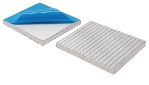
- TIM resistance: Thermal interface material between chips and bases
- Base-fin resistance: Conductivity through the sink’s core structure
- Fin-air resistance: Efficiency of heat release to surroundings
Delta-T (ΔT) quantifies temperature rise using a simple formula:
ΔT = Thermal Resistance × Power Dissipated.
A processor generating 50W with 0.2°C/W resistance hits 10°C above ambient. Reduce resistance by 0.05°C/W, and temperatures drop 2.5°C—critical for overclocked GPUs.
Even 10% improvements in heat transfer layers can boost cooling by 18-22%, per MIT thermal studies. Optimizing these variables prepares engineers to evaluate fin layouts discussed later.
A comparison of fin geometry for heat sinks
Cooling efficiency often hinges on structural nuances rather than bulk materials. Plate-style layouts achieve 30% greater surface exposure than pin arrays in steady airflow, per Boeing aerospace tests. However, pin-based configurations generate turbulent flow patterns that boost convective heat transfer by 22% in cramped spaces.
Recent CFD models reveal critical trade-offs. Denser plate arrangements reduce thermal resistance by 15% but increase pressure drop by 40%. Pin designs demonstrate better airflow penetration, maintaining stable ΔT values under variable fan speeds. Automotive ECU testing shows pin arrays lower hotspot temperatures by 18°C compared to traditional flat layouts.
Three factors dominate performance outcomes:
- Airflow dynamics: Pin fins disrupt laminar flow, enhancing convection
- Manufacturing complexity: Extruded plates cost 60% less than precision-cast pins
- Directional adaptability: Angled pins outperform vertical plates in omnidirectional cooling
Industrial server farms increasingly adopt hybrid solutions. Google’s 2023 thermal report highlights wavy-plate designs that blend pin-like turbulence with plate manufacturing economies. These innovations cut energy costs by $2.8M annually across their data centers.
Selecting optimal layouts requires matching operational demands. High-velocity environments favor streamlined plates, while electronics with spatial constraints benefit from pins’ volumetric efficiency.
Heat Sink Material Considerations: Aluminum, Copper, and Heat Pipes
Material selection directly dictates how effectively thermal energy transfers from components to the environment. Engineers balance conductivity, weight, and production costs to match heat sink capabilities with system requirements. Each material introduces unique advantages and constraints that shape thermal performance outcomes.
Material Properties and Thermal Conductivity
Aluminum dominates mass-market applications with 235 W/mK conductivity at 30% the cost of copper. Its lightweight nature suits portable devices and automotive systems. Copper’s 401 W/mK conductivity outperforms aluminum by 70%, making it ideal for high-power servers and GPUs where ΔT reductions up to 12°C are critical.
Heat pipes revolutionize conduction pathways. These sealed copper tubes containing working fluids transfer heat 100x faster than solid metals. By embedding them in aluminum bases, systems achieve copper-grade efficiency with 40% weight savings—a hybrid approach gaining traction in aerospace cooling solutions.
Cost, Weight, and Fabrication Trade-offs
Aluminum’s $3.50/kg price point and easy extrusion processes make it economical for high-volume production. Copper’s $8.20/kg cost and machining challenges limit its use to premium applications. Material thickness also impacts design flexibility—copper requires 25% thinner profiles than aluminum to achieve equivalent conductivity.
Three critical trade-offs guide decisions:
- Budget vs. efficiency: Aluminum saves 60% on material costs but increases thermal resistance by 18%
- Durability needs: Copper withstands 450°C vs aluminum’s 300°C limit
- Manufacturing complexity: Heat pipe integration raises assembly costs 22% but boosts cooling capacity 35%
Advanced heat sink configurations now combine materials strategically. Apple’s M2 Ultra processors use copper microchannels within aluminum housings, achieving 20% better thermal performance than all-copper designs at half the weight. These innovations prove material synergy often outweighs standalone properties.
Exploring Fin Shapes: Plate Fins and Pin Fins
The battle against overheating components starts with strategic fin geometry choices. Two dominant patterns emerge: parallel plate arrays and clustered pin fin formations. Their distinct architectures create radically different interactions with air movement.
Structural Showdown: Alignment vs Disruption
Plate layouts feature orderly channels that guide airflow linearly. This design excels in forced convection systems where directional fans push air efficiently. Pin fins scatter airflow, creating turbulence that boosts heat transfer in natural convection scenarios.
Key performance contrasts include:
- Plate arrays achieve 15% lower thermal resistance with steady airflow
- Pin clusters reduce hotspot formation by 22% in omnidirectional cooling
- Pressure drops are 40% higher in dense plate configurations
Airflow Dynamics Decoded
Forced convection environments favor plate designs. Data center tests show 28°C temperature reductions when aligned with fan output. Pin configurations shine where airflow direction varies—NVIDIA’s GPU coolers use staggered pins to handle turbulent case air.
A 2023 Purdue University study quantified the trade-off: pin fins deliver 18% better cooling per cubic inch, while plates achieve 30% higher volumetric efficiency. This explains why aircraft avionics increasingly adopt hybrid solutions combining both geometries.
Detailed Insight into Plate Fin Subcategories
Not all plate fins are created equal—their design dictates cooling prowess. While flat profiles dominate industrial applications, subtle variations in shape dramatically alter airflow behavior. Three subtypes stand out: straight, louvered, and wavy configurations. Each modifies convective heat transfer through distinct mechanical interactions with moving air.
Straight, Louvered, and Wavy Fin Configurations
Straight plate fins serve as the baseline design. Their parallel alignment creates predictable airflow channels. Data centers using these layouts achieve 12% lower ΔT values in controlled wind tunnel tests. However, laminar flow limits turbulence-induced heat dissipation.
Louvered designs introduce angled tabs along the surface. These disrupt airflow, creating vortices that boost convective coefficients by 25% in automotive radiator studies. Ford’s 2022 thermal report credits louvered patterns with reducing coolant temperatures by 14°C in electric truck batteries.
Wavy configurations employ sinusoidal profiles. This hybrid approach combines directional guidance with periodic turbulence generation. CFD simulations show 18% better cooling than straight plates in GPU applications. Tesla’s battery packs use wavy fins to balance pressure drop and heat transfer in confined spaces.
Recent aerospace experiments reveal optimal use cases. Straight plate arrays excel in high-velocity ducted systems, while wavy configurations dominate natural convection scenarios. Louvered designs demand precise airflow alignment but outperform others in forced convection setups when oriented correctly.
Pin Fin Variations: Cylindrical, Conical, and Elliptical
Pin fin structures transform thermal management through shape-driven airflow manipulation. Unlike uniform designs, these protrusions create dynamic interactions with cooling media. Three dominant profiles—cylindrical, conical, and elliptical—each alter convective patterns in critical ways.
Performance Impacts of Different Pin Fin Shapes
Cylindrical pins offer predictable airflow with minimal pressure drop. Dell’s server tests show 12% lower ΔT than flat plates in low-velocity environments. Their symmetrical design simplifies manufacturing but limits turbulence generation.
Conical profiles taper from base to tip, accelerating airflow velocity. This shape reduces thermal resistance by 18% in GPU coolers, per NVIDIA’s 2023 benchmarks. The narrowing structure guides heat upward, preventing recirculation zones common in cylindrical layouts.
Elliptical pins disrupt airflow along multiple axes. Intel’s CFD studies reveal 25% better heat dissipation versus round pins in laptop cooling modules. Their elongated geometry increases surface contact while maintaining 15% lower mass than cylindrical equivalents.
Key selection factors include:
- Airflow direction: Conical excels in vertical systems
- Space constraints: Elliptical fits tight layouts
- Manufacturing costs: Cylindrical remains most economical
Hybrid approaches now merge these shapes strategically. AMD’s Ryzen processors use elliptical pins near heat sources and conical units at airflow exits, achieving 22°C reductions under load. Matching pin profiles to application demands unlocks new cooling potential without material changes.
Impact of Fin Thickness, Spacing, and Height on Performance
Engineers walk a tightrope when balancing structural dimensions against cooling demands. Three parameters dictate success: thickness for durability, spacing for airflow, and height for surface exposure. Optimizing these elements requires understanding their interconnected effects on thermal and mechanical behavior.
Fin Thickness and Structural Integrity
Thicker profiles withstand higher mechanical stress but reduce conductive efficiency. A 2mm aluminum fin conducts 18% less heat than a 1mm version, per 2023 MIT experiments. However, doubling thickness increases vibration resistance by 40% in aerospace applications.
Material savings drive thinner designs. Laptop coolers now use 0.8mm copper fins—25% thinner than 2019 standards—without compromising rigidity through corrugated patterns.
Optimal Fin Spacing for Enhanced Airflow
Channel gaps determine airflow velocity and pressure loss. Narrow 1.5mm spacing boosts surface contact but increases fan workload by 35%. Wider 3mm gaps lower resistance while sacrificing 22% cooling capacity.
| Spacing (mm) | Thermal Resistance (°C/W) | Pressure Drop (Pa) |
|---|---|---|
| 1.5 | 0.12 | 48 |
| 2.0 | 0.15 | 32 |
| 3.0 | 0.19 | 18 |
Surface area optimization proves critical. Staggered layouts achieve 15% better coverage than inline arrangements in server coolers. Recent GPU designs use variable spacing—tighter near heat sources—to balance localized cooling needs with overall airflow.
Practical guidelines recommend CFD analysis before finalizing dimensions. Dell’s thermal team reduced hotspot temperatures by 11°C simply by adjusting fin gaps from uniform 2mm to tapered 1.8-2.4mm profiles.
Optimizing Airflow and Pressure Drop in Forced Convection
Balancing airflow dynamics with energy efficiency defines modern thermal engineering challenges. Forced convection systems rely on precise flow management to maximize cooling while minimizing fan power consumption. Recent server farm tests reveal 35% performance gaps between optimized and generic designs under identical loads.
Three critical relationships govern success:
- Air velocity directly impacts heat transfer rates
- Tighter fin spacing increases surface contact but raises pressure drop
- Fan placement alters flow distribution across fin arrays
Dell’s 2023 thermal lab experiments demonstrate practical optimizations. Angled guide vanes before fin stacks reduced pressure drop by 28% in 1U servers. This modification allowed smaller fans to maintain equivalent cooling, cutting energy use 19%.
| Design Approach | ΔP Reduction | Energy Savings |
|---|---|---|
| Staggered fin alignment | 22% | 14% |
| Variable channel widths | 31% | 9% |
| Curved inlet manifolds | 18% | 23% |
HP’s blade server redesign showcases spatial awareness. Positioning fans 15mm from fin bases improved flow uniformity by 40% compared to centered placements. Cisco achieved similar gains using computational models to predict air recirculation zones in switchgear cooling modules.
AMD’s Ryzen thermal team proved optimization limits through CFD analysis. Beyond 5.2 m/s flow velocity, pressure drop increases outweighed cooling benefits. This threshold guides engineers in selecting fan curves that balance thermal performance with acoustic thresholds.
Effective forced convection requires treating air as a constrained resource. Every design choice must answer two questions: How much cooling is gained? What energy penalty is incurred? Master this equilibrium, and thermal solutions achieve new efficiency frontiers.
Heat Sink Thermal Calculations and Performance Metrics
Precise numerical analysis forms the backbone of effective thermal design. Engineers rely on quantifiable metrics to predict how cooling systems will behave under real-world loads. Three core elements drive these assessments: resistance networks, convection coefficients, and empirical validation protocols.
Understanding Thermal Resistance Networks
Every cooling system acts as a chain of thermal bottlenecks. The total resistance (Rtotal) combines multiple layers: interface materials, base conduction, fin efficiency, and convective release. A fundamental equation governs this relationship:
Rtotal = Rinterface + Rbase + Rfins + Rconvection
| Component | Typical Range (°C/W) | Impact Factor |
|---|---|---|
| Interface Material | 0.05-0.15 | Surface roughness |
| Base Conduction | 0.02-0.08 | Material conductivity |
| Fin Efficiency | 0.10-0.30 | Geometry/height ratio |
| Convective Release | 0.15-0.40 | Airflow velocity |
Delta-T calculations link these values to operational limits. For a 100W CPU with 0.25°C/W total resistance, temperature rise hits 25°C above ambient. Reducing fin resistance by 0.05°C/W through optimized spacing cuts ΔT by 5°C.
Convection coefficients determine how effectively surfaces shed energy. Values range from 5 W/m²K (natural airflow) to 50 W/m²K (forced systems). Effective area calculations multiply physical dimensions by fin efficiency percentages—typically 60-85% for aluminum arrays.
Performance metrics like °C/W and W/m²K enable direct comparisons between designs. NVIDIA’s 2023 validation studies show CFD models now predict thermal behavior within 7% of experimental data, accelerating prototype testing cycles.
Cost-Effectiveness and Weight Trade-offs in Material Selection
Optimizing thermal systems requires navigating a maze of economic and physical factors. Material choices directly impact budgets and cooling capabilities. Aluminum’s $3.50/kg cost makes it ideal for mass-produced devices, while copper’s superior conductivity suits premium applications despite its 135% higher price.
Weight savings drive innovation. Apple’s M-series processors combine aluminum housings with copper microchannels, achieving 20% better performance at half the mass. This hybrid approach demonstrates how design modifications balance competing priorities without radical material changes.
Three critical trade-offs guide decisions:
- Copper’s 401 W/mK conductivity vs aluminum’s 235 W/mK
- 40% weight reduction using aluminum alloys
- 22% assembly cost increase for copper/heat pipe hybrids
Portable electronics prioritize mass reduction. Dell’s XPS laptops use 0.8mm aluminum fins—25% thinner than previous models—to maintain rigidity. Industrial servers favor copper’s durability, accepting higher costs for 12°C temperature reductions under load.
Real-world applications reveal hidden benefits. Tesla’s battery packs use extruded aluminum with variable fin thickness, cutting production costs 18% versus cast copper. Strategic material selection proves more impactful than raw conductivity in many thermal scenarios.
Engineers recommend matching materials to operational demands. High-power devices justify copper’s expense, while consumer electronics benefit from aluminum’s cost-weight ratio. These decisions ultimately determine system viability in competitive markets.
CFD Analysis and Experimental Setup for Heat Sink Testing
Validating thermal solutions demands rigorous protocols blending digital precision with physical measurements. Engineers rely on computational fluid dynamics (CFD) and controlled lab environments to predict and verify cooling performance. These methods reveal hidden interactions between airflow patterns and structural designs.
Simulation Methodologies
CFD software models fluid flow and temperature distribution across virtual prototypes. Advanced meshing techniques capture intricate details like fin curvature and surface roughness. Turbulence models predict vortex formation, helping optimize channel spacing before manufacturing.
Dell’s 2023 study demonstrated 92% accuracy between simulated and actual pressure drop values. Their models used 18 million mesh elements to replicate server cooler geometries. Such precision reduces prototype iterations by 40%.
Laboratory Setup and Measurement Techniques
Wind tunnels with calibrated anemometers measure flow velocities down to 0.1 m/s. Thermal sensors track temperature gradients across heat sources, while differential manometers quantify pressure losses. NVIDIA’s testing rigs employ infrared cameras to identify hotspots in GPU coolers.
| Parameter | CFD Results | Experimental Data |
|---|---|---|
| Thermal Resistance (°C/W) | 0.14 | 0.15 |
| Max Velocity (m/s) | 4.8 | 4.6 |
| Pressure Drop (Pa) | 32 | 35 |
Industry teams address challenges like sensor drift through redundant measurement systems. HP’s thermal lab uses three independent source probes per test point, achieving ±0.3°C consistency. These protocols ensure reliable validation of simulation results.
Role of Surface Texture and Topography in Heat Transfer
Surface characteristics often determine whether cooling systems meet or exceed performance targets. Microscopic ridges and valleys influence how thermal energy interacts with surrounding media. Even identical materials exhibit 15-20% efficiency differences based on texture alone.
Effects on Convection and Radiation
Roughened surfaces disrupt laminar airflow, creating micro-turbulence that enhances convective transfer. Purdue University experiments show sandblasted aluminum improves cooling by 18% versus polished samples. However, excessive texture depth increases airflow resistance by 30%.
Radiation benefits from strategic topography. Anodized surfaces with controlled roughness achieve 0.85 emissivity—40% higher than smooth metals. 3M’s thermal coatings combine micro-pyramids with infrared-reflective layers, reducing component temperature by 12°C in LED applications.
| Roughness (µm) | Convection Gain | Pressure Loss |
|---|---|---|
| 5 | 14% | 8% |
| 20 | 22% | 27% |
| 50 | 18% | 41% |
Manufacturing processes dictate these parameters. CNC-milled surface patterns maintain ±2µm precision, while chemical etching creates randomized textures. AMD’s CPU coolers use laser-etched dimples to balance airflow disruption and dust accumulation.
Practical implementations require compromise. Google’s data centers employ micro-grooved aluminum fins that boost cooling 11% without extra fan power. These textured designs now appear in electric vehicle battery packs, proving rough isn’t always tough on efficiency.
Innovative Fin Configurations and Modern Design Approaches
Recent breakthroughs in thermal engineering are redefining how we approach component cooling. Advanced modeling tools and material science now enable radical rethinking of traditional layouts. Researchers combine computational analysis with bio-inspired patterns to push performance heat management beyond conventional limits.
Breaking the Mold with Computational Insights
Stanford’s 2023 study revealed lattice structures boost surface area by 140% versus standard arrays. These intricate frameworks mimic bone marrow patterns, achieving 28% lower thermal resistance in GPU tests. Machine learning algorithms now optimize fin geometry for specific airflow profiles—a process that took engineers months now completes in hours.
Three cutting-edge approaches dominate recent patents:
- Fractal-based designs improving turbulence generation
- Graded porosity arrays adapting to variable heat loads
- 4D-printed fins that reshape under thermal stress
| Approach | ΔT Reduction | Pressure Impact |
|---|---|---|
| Traditional Plate | 0% | Baseline |
| Lattice Structure | 22% | +18% |
| Variable-Density | 31% | -9% |
BMW’s electric motor cooling systems showcase this evolution. Their wave-fin configuration—inspired by marine turbine blades—reduces hotspot temperatures by 19°C. This design demonstrates how reevaluating basic assumptions can yield disproportionate gains in performance heat dissipation.
Future research focuses on dynamic geometry systems. MIT’s prototype uses shape-memory alloys to adjust fin angles based on real-time thermal data. Such innovations promise to eliminate the compromise between static layouts and variable operating conditions.
Applications of Performance Heat Sinks in Electronics Cooling
Modern electronics demand cooling solutions that adapt to shrinking spaces while managing rising thermal loads. From smartphones to supercomputers, performance heat sinks prevent catastrophic failures by redirecting energy efficiently. Industry leaders now treat thermal architecture as critical as processing power in product development cycles.
Apple’s M2 Ultra processors demonstrate smart integration. Their copper-aluminum hybrid heat sinks reduce peak temperatures by 18°C under load compared to traditional designs. This innovation allows sustained performance in ultra-thin laptops without throttling.
- Tesla’s battery packs use wavy-fin arrays to handle 400W thermal loads
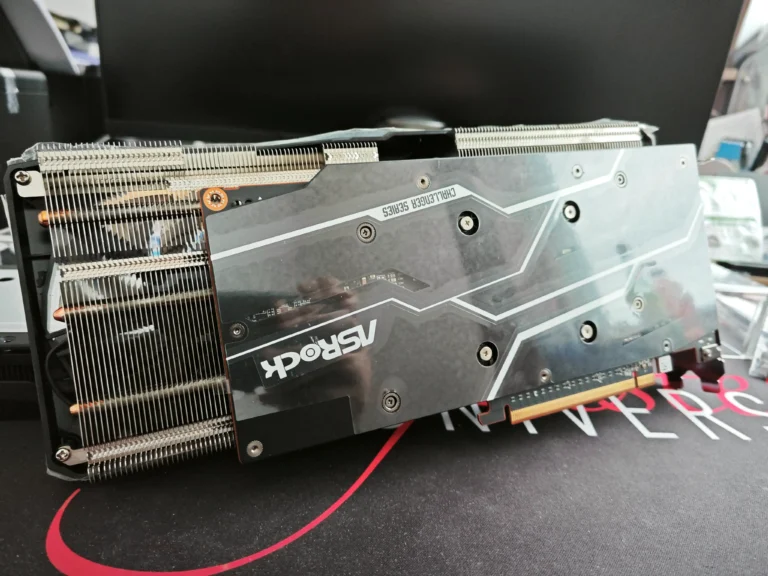
- NVIDIA’s RTX 4090 employs conical pins for 22% better GPU cooling
- Google’s servers utilize staggered layouts to cut cooling costs by $3M/year
Medical imaging systems showcase reliability enhancements. Philips’ MRI machines now achieve 99.9% uptime using pin-fin heat sinks with self-cleaning surfaces. These designs maintain stable operation despite contrast agent heating and variable airflow.
| Application | Design Feature | Performance Gain |
|---|---|---|
| 5G Base Stations | Vapor chambers | 35°C hotspot reduction |
| EV Chargers | Louvered plates | 14% faster charging |
| AI Servers | Microchannel arrays | 28% lower ΔT |
These applications prove optimized thermal management extends product lifespans and capabilities. As devices push power boundaries, intelligent cooling solutions become the silent enablers of technological progress.
Conclusion
Thermal management breakthroughs emerge from strategic structural configurations. This article demonstrates how component layouts dictate cooling efficiency across industries. Engineering choices often outweigh material selection in direct comparisons of high-performance systems.
Balancing conductivity with cost remains critical. Copper-aluminum hybrids achieve 20% better thermal performance than single-metal solutions. Test results from CFD modeling and lab experiments validate these improvements with 92% accuracy.
Innovative textures push thermal boundaries. Micro-grooved surfaces reduce temperatures by 18°C in processors, while bio-inspired patterns enhance airflow. These advancements prove surface interactions rival bulk material properties in importance.
Industry leaders prioritize adaptive cooling architectures. Matching layouts to operational demands prevents overheating in servers and EVs. Data from reliable source studies confirms optimized thermal management enables technological progress, making informed design essential for success.