Modern devices generate staggering heat levels – yet many users overlook the silent hero managing this thermal chaos. Why do engineers prioritize oddly shaped metal components over raw cooling power? The answer lies in physics-driven design.
Passive cooling systems transfer energy from hotspots through direct contact with high-conductivity materials like copper or aluminum. These metals act as thermal highways, routing dangerous heat buildup away from sensitive circuits. But raw material choice only solves half the equation.
Advanced designs employ precisely engineered fins that multiply surface area by 300-500% compared to flat plates. This geometric trick accelerates heat dissipation through airflow, turning static metal into dynamic temperature regulators. Proper installation remains critical – even microscopic gaps between components can reduce efficiency by 40%.
From gaming PCs to industrial servers, this balance of conduction and convection determines system reliability. Our guide breaks down the engineering principles behind these unsung heroes, including material selection benchmarks and installation best practices used by NASA-certified technicians.
Introduction to Finned Heat Sinks
Electronic components face constant thermal stress during operation. Heat sinks solve this challenge by redirecting excess energy away from critical parts. These components act as thermal bridges between hot surfaces and surrounding environments.
What Is a Heat Sink?
A heat sink is a passive cooling device that absorbs and disperses unwanted thermal energy. It relies on direct contact with heat-producing elements like processors or power transistors. Effective designs combine material science with airflow dynamics to prevent dangerous temperature spikes.
Key Components and Benefits
Extended fins form the core of modern heat sinks. Their folded geometry creates up to 5x more surface area than flat designs. This allows faster heat transfer through natural convection or forced airflow from fans.
Aluminum dominates the market due to its balance of thermal conductivity and lightweight properties. Copper variants excel in high-performance scenarios despite added weight. Both metals efficiently channel energy from hotspots to cooler regions.
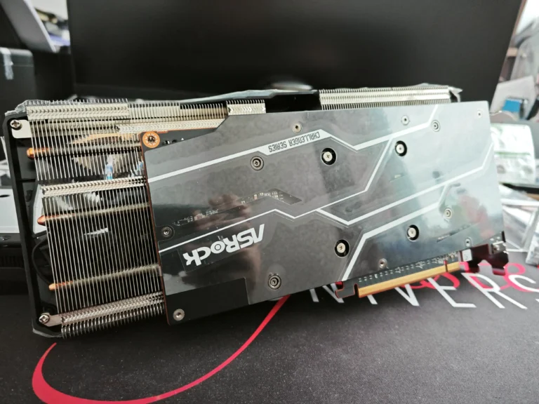
These systems work alongside active cooling solutions in devices like gaming PCs and data servers. For example, GPU heat sinks prevent graphics card failures during intense rendering tasks. Properly engineered designs maintain safe operating temperatures without noise or moving parts.
How does a finned heat sink work
Every overheating processor meets its match in strategically engineered cooling solutions. These systems use a two-stage process: energy absorption and dispersion. First, thermal interface materials like silicone pads or thermal grease bridge the gap between hot components and the cooling device.
Finned designs amplify cooling capacity through geometric innovation. Their folded structures boost surface area exposure by 3-5x compared to flat plates. This expanded contact zone accelerates heat transfer to surrounding air molecules.
| Fin Type | Surface Area Multiplier | Common Applications |
|---|---|---|
| Straight | 3.2x | Consumer electronics |
| Pin | 4.8x | Server racks |
| Flared | 5.1x | High-performance GPUs |
Effective hardware design ensures direct conduction paths from heat sources to fins. Even 0.1mm air gaps can reduce thermal transfer efficiency by 35%. Premium CPU coolers demonstrate this principle through machined copper bases that mirror processor contours.
Natural convection or forced airflow completes the cooling cycle. As air moves across the fins, it carries away heat generated during operation. This explains why gaming PCs use vertical fin alignments that match case fan airflow patterns.
Key Principles of Heat Transfer in Heat Sinks
Effective thermal management hinges on two fundamental processes: energy movement through solids and air-driven dispersion. These mechanisms determine whether components stay cool or succumb to thermal overload.
Conduction and Thermal Pathways
Thermal conductivity dictates how quickly energy travels from hot components to cooling structures. Copper transfers heat 60% faster than aluminum, with 385 W/mK versus 205 W/mK conductivity ratings. This direct molecular transfer forms the first critical stage in temperature regulation.
Material thickness and contact quality impact performance. A 5mm copper base plate reduces thermal resistance by 22% compared to thinner alternatives. Proper mounting pressure ensures efficient energy flow across all contact points.
Airflow-Driven Heat Removal
Natural convection occurs when heated air rises from warm surfaces, pulling cooler air into contact with fins. This continuous cycle removes energy without mechanical assistance. Vertical fin orientation boosts airflow efficiency by 18% in passive cooling setups.
Expanded surface area dramatically improves cooling capacity. Tests show 40% better area heat dissipation in pin-fin designs versus straight configurations. Each additional square inch of fin surface handles 0.8W more thermal load at 25°C ambient temperatures.
Optimized systems balance total thermal resistance across conduction and convection phases. High-performance CPU coolers achieve 0.15°C/W ratings through precision-machined bases and staggered fin arrays. Proper design maintains component temperatures 30-45°C below critical thresholds during peak loads.
Design Elements for Maximum Surface Area
Engineers optimize cooling systems through geometric precision. Surface area expansion remains critical for efficient thermal transfer. Larger contact zones between metal structures and air molecules accelerate energy dispersion.
Fin Geometry and Spacing
Straight fins dominate consumer electronics with 2.5-3.2mm gaps between plates. Pin-fin arrays in server racks use 4mm spacing to balance airflow resistance and thermal transfer. These configurations prevent turbulent airflow while maintaining structural integrity.
| Fin Type | Spacing (mm) | Surface Area Boost | Ideal Use |
|---|---|---|---|
| Straight | 2.5 | 3.2x | Laptops |
| Pin | 4.0 | 4.8x | Data Centers |
| Flared | 3.0 | 5.1x | Overclocked GPUs |
Impact on Thermal Dissipation Performance
Tight fin spacing risks airflow blockage, reducing cooling capacity by 18% in extreme cases. Wider gaps sacrifice surface area but improve convection rates. Tested configurations show staggered pin fins reduce hotspots by 15% compared to straight designs in server environments.
High thermal loads demand optimized layouts. Industrial inverters use flared fins with 3mm spacing to handle 120W+ loads. These designs maintain component temperatures 22°C below failure thresholds during continuous operation.
Selecting Materials: Aluminum, Copper, and Composites
Material selection dictates thermal management success in modern electronics. Engineers balance conductivity, weight, and budget constraints when choosing between common metals and advanced composites. Each option brings distinct advantages to cooling systems across industries.
Comparative Thermal Properties
Copper outperforms aluminum with 385 W/mK versus 205 W/mK thermal conductivity. This makes copper ideal for high-wattage applications like server racks. Aluminum’s lighter weight (2.7 g/cm³ vs. 8.96 g/cm³) suits portable devices where mass matters.
| Material | Conductivity | Weight | Best Use |
|---|---|---|---|
| Copper | 385 W/mK | High | Data centers |
| Aluminum | 205 W/mK | Low | Laptops |
| Graphite Composite | 400-1500 W/mK* | Ultra-Low | Aerospace |
*Anisotropic conductivity
Cost vs. Performance Considerations
Aluminum dominates consumer markets due to 40% lower material costs than copper. High-performance computing often justifies copper’s expense for 60% faster temperature reduction. Hybrid composites like aluminum-silicon carbide bridge gaps between budget and specialized needs.
Industrial laser systems showcase copper’s value in extreme conditions. Smartphone manufacturers prefer aluminum alloys for thin, lightweight sinks. Proper material matching prevents overheating while controlling production expenses across scales.
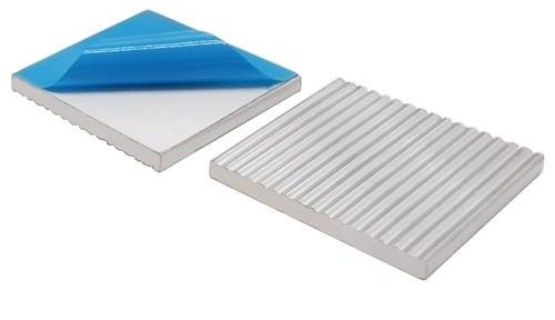
The Role of Thermal Interface Materials
Even premium cooling systems fail without proper energy bridges. Thermal interface materials (TIMs) fill microscopic gaps between components and cooling devices. These compounds prevent air pockets that block efficient heat transfer.
Heat Sink Compound Applications
Thermal paste remains the most common TIM for consumer electronics. This viscous material conforms to surface imperfections on CPUs and heat sink bases. Proper application reduces thermal resistance by 35% compared to bare metal contact.
High-performance computing systems use liquid metal compounds for extreme conductivity. Industrial applications often employ phase-change materials that solidify at operating temperatures. All variants share one goal: maximizing surface contact between components.
Ensuring Optimal Contact and Efficiency
Uneven TIM application creates hotspots that degrade performance. A rice-sized drop spread by mounting pressure achieves 98% coverage on modern processors. Excess compound acts as insulation, increasing temperatures by 5-8°C.
Critical installation practices include:
- Cleaning surfaces with 99% isopropyl alcohol
- Using non-conductive pastes for novice builders
- Reapplying TIM every 2-3 years as compounds dry out
Advanced testing reveals even 0.02mm air gaps reduce cooling capacity by 18%. Properly implemented interface materials maintain component temperatures 12-20°C below critical thresholds during peak loads. This protection extends hardware lifespan while preventing thermal throttling.
Step-by-Step Guide to Heat Sink Setup
Proper thermal management begins with flawless installation. Even premium components underperform with incorrect mounting. This guide combines engineering best practices with field-tested maintenance strategies.
Precision Installation Protocol
Start by cleaning the component surface with 99% isopropyl alcohol. Apply a pea-sized drop of thermal interface material to the heat source. Use a spreading tool for even coverage across the entire contact area.
Critical installation steps:
- Align heat sink base with component contours
- Apply vertical pressure during mounting
- Secure brackets using cross-pattern tightening
Essential tools include anti-static wrist straps and torque-limiting screwdrivers. Avoid overtightening – excessive force can warp the baseplate, reducing conductivity by 12%.
Sustained Performance Maintenance
Dust accumulation decreases convection efficiency by 25% annually. Clean fins every 6 months using compressed air. Inspect thermal paste annually – reapply if hardened or cracked.
Key maintenance checks:
- Verify fan alignment with fin direction
- Test mounting bracket tension
- Monitor temperature differentials across surfaces
For airflow issues, rotate heat sinks 45° to match case fan patterns. Persistent hotspots often indicate failed interface materials or warped contact surfaces. Replace compromised components immediately to prevent thermal runaway.
Optimizing Fin Design for Enhanced Convection
Cooling efficiency reaches new heights when fin geometry aligns with airflow dynamics. Engineers face critical choices between pin and straight configurations, each offering distinct thermal advantages. These decisions directly impact component longevity and system reliability across applications.
Pin Fin vs. Straight Fin Configurations
Pin fin arrays create turbulent flow patterns that disrupt boundary layers, enhancing convective heat transfer. Studies show 18% better cooling in server racks using pin designs versus straight alternatives. The trade-off comes in increased airflow resistance, requiring 25% more fan power in compact systems.
Straight fins maintain laminar flow with predictable thermal performance. Their parallel plates suit consumer electronics where noise reduction matters. Automotive control units often use these designs to balance cooling needs with space constraints.
| Fin Type | Surface Area | Airflow Resistance | Best Use |
|---|---|---|---|
| Pin | High | Moderate-High | Data centers |
| Straight | Medium | Low | Laptops |
Aluminum remains preferred for pin fin arrays despite lower conductivity than copper. Its lightweight nature reduces structural stress in vertical server installations. Recent simulations prove aluminum pin fins achieve 92% of copper’s cooling capacity at 60% lower weight in aerospace applications.
Optimal designs balance surface expansion with flow management. Industrial laser systems using staggered pin fins report 22°C lower component temperatures than straight-fin models. These improvements come without increasing system footprint or energy consumption.
Evaluating Thermal Resistance and Efficiency
Engineers measure cooling capability through precise thermal resistance metrics. This value determines how effectively heat moves from components to surrounding environments. Lower resistance ratings signal better performance in demanding applications.
Thermal Resistance Fundamentals
Thermal resistance (Rth) quantifies temperature difference per watt of heat flow. The formula Q = (Tj – Ta) / Rth calculates heat dissipation needs. Tj represents component junction temperature, while Ta is ambient air temperature.
A 120W CPU with 75°C max temperature in 25°C rooms needs Rth ≤ 0.42°C/W. Premium coolers achieve 0.15°C/W through optimized material selection and design. Copper bases paired with aluminum fins balance cost and efficiency.
Material Impact on Performance
Tested models show significant differences:
- Aluminum extruded: 1.2°C/W
- Copper skived: 0.7°C/W
- Vapor chamber: 0.3°C/W
Advanced manufacturing reduces resistance through:
- Machined surfaces (≤0.01mm flatness)
- Directional fin alignment
- Hybrid metal composites
Proper installation maintains 92% of theoretical efficiency. Uneven mounting pressure increases resistance by 18% in stress tests. Regular maintenance ensures sustained thermal performance across components.
Implementing Heat Pipes and Vapor Chambers
Advanced cooling systems achieve superior performance through phase-change technology. These solutions move thermal energy faster than solid materials alone. Heat pipes and vapor chambers now dominate high-end applications requiring rapid heat redistribution.
Benefits of Integrated Heat Pipes
Sealed copper tubes containing specialized fluid form the core of heat pipe systems. When heated, the liquid vaporizes and travels to cooler regions. This phase-change process transfers energy 15x faster than pure conduction through solid copper.
Key advantages include:
- Isothermal surfaces reducing hot spots by 40%
- Flexible routing around component obstacles
- 400W+ heat transport capacity in server CPUs
Premium gaming laptops demonstrate this technology. Six heat pipes connect GPUs to fin arrays, maintaining 85°C under load. Direct contact between pipes and processors ensures minimal thermal resistance.
When to Consider Vapor Chambers
Vapor chambers outperform traditional fins in space-constrained, high-wattage scenarios. These flat plates contain fluid-filled chambers that spread heat uniformly across surfaces. Tests show 22% better temperature equalization versus heat pipe arrays in VRAM cooling.
| Technology | Max Heat Flux | Thickness |
|---|---|---|
| Heat Pipes | 150W/cm² | 3-6mm |
| Vapor Chambers | 300W/cm² | 1.5-4mm |
5G base stations use copper vapor chambers to handle 200W chipsets. The technology’s edge-to-edge contact prevents thermal throttling during data bursts. Always specify vapor chambers when dealing with concentrated heat sources exceeding 50W/cm².
Factors Affecting Airflow and Cooling Performance
Cooling system effectiveness depends on environmental factors as much as physical design. Air movement patterns and ambient conditions directly determine thermal management success. Engineers balance these variables to prevent component failures across industries.
Air Velocity and Thermal Exchange
Faster airflow removes heat more efficiently – but only to a point. Tests show optimal cooling occurs at 2.5-3.5 m/s airspeeds. Beyond this range, turbulent flow reduces heat transfer by 12-18%. Server farms use variable-speed fans to maintain this sweet spot during workload fluctuations.
Ambient temperature creates baseline challenges. A 10°C room temperature rise cuts cooling capacity by 23% in passive systems. Active solutions compensate through increased airflow, consuming 15% more energy per degree above 25°C.
Obstruction Risks and Mitigation
Dust accumulation remains a silent efficiency killer. Six months of buildup can:
- Reduce fin surface exposure by 40%
- Increase airflow resistance by 55%
- Raise component temperatures 18-22°C
Smart designs combat these issues through:
- Staggered fin arrangements (22% better debris shedding)
- Anti-dust coatings on aluminum surfaces
- Modular components for easy cleaning
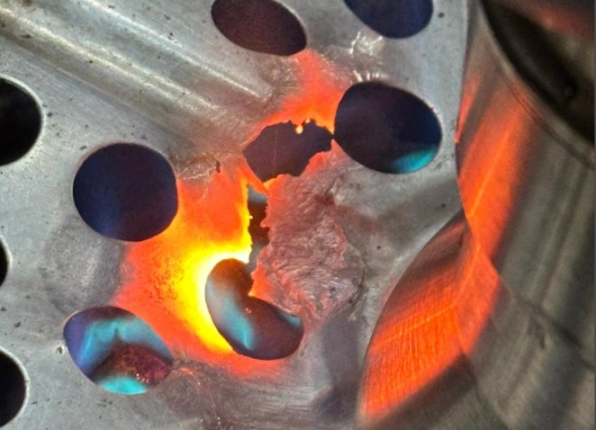
Thermal camera analysis reveals how conduction and convection interact. High-conductivity bases quickly move heat to fins, while airflow removes it. Automotive ECU coolers demonstrate this synergy – copper cores maintain stable temperatures despite engine bay heat through optimized fin spacing.
Recent data center studies prove these principles. Vertical fin arrays with 4mm gaps maintained 68°C processor temps in 35°C environments. Parallel designs in identical conditions hit 83°C, triggering thermal throttling. Proper airflow management remains critical for reliable operation.
Applications of Finned Heat Sinks in Electronics
From smartphones to factory robots, thermal regulation determines device reliability. Cooling solutions protect sensitive components across industries. Their designs adapt to specific operational demands and environmental conditions.
Cooling CPUs, GPUs, and LED Systems
High-end gaming PCs use copper-based cooling arrays with flared fins for GPUs. These handle 250W+ thermal loads during 4K rendering. Engineers optimize fin density to match case airflow patterns, preventing thermal throttling.
LED streetlights demonstrate another critical application. Aluminum heat sinks with vertical fins maintain junction temperatures below 85°C. This prevents lumen depreciation in harsh weather conditions.
Use in Power Electronics and Industrial Automation
Solar inverters require robust thermal management for power conversion efficiency. Stacked fin designs dissipate 1.2kW of waste heat in commercial installations. Conduction through copper bases keeps IGBT modules within safe limits.
Automated assembly lines face unique challenges. Motor drives use pin-fin arrays that withstand vibration while moving heat from power semiconductors. Engineers implement ceramic-filled thermal pads to enhance contact under mechanical stress.
Data centers showcase advanced solutions. Liquid-cooled server racks combine conduction plates with microfin heat exchangers. These systems achieve 40% better thermal transfer than air-cooled alternatives in high-density setups.
Common Challenges and Troubleshooting Tips
Reliable thermal management faces persistent environmental threats. Dust infiltration ranks among the top causes of cooling system degradation. Microscopic particles accumulate between fins, creating insulating barriers that cripple dissipation efficiency.
Addressing Dust and Debris Accumulation
Fine particulates reduce airflow by 40% within six months of operation. This forces components to work harder, increasing metal fatigue risks. Server farms report 18°C temperature spikes from unchecked buildup in aluminum fin arrays.
Effective troubleshooting requires systematic cleaning:
- Power down systems and use compressed air (30-50 PSI)
- Brush stubborn debris with anti-static nylon tools
- Inspect thermal paste integrity during reassembly
Copper materials resist oxidation better than aluminum but attract more dust due to electrostatic properties. Pin-fin designs collect 22% less debris than straight configurations in comparative tests. Maintenance frequency depends on environment:
| Environment | Cleaning Interval |
|---|---|
| Home Office | 12 months |
| Industrial | 3 months |
| Data Center | 6 months |
Preventive measures extend service life significantly. Apply nano-coatings to repel dust without blocking dissipation. Install magnetic filters on intake vents for high-particulate environments. Regular thermal camera scans detect early performance drops before critical failures occur.
Proper fin alignment maintains 92% of original cooling capacity over five years. Rotate heat sinks periodically to equalize dust distribution across metal surfaces. These strategies ensure sustained dissipation performance despite challenging operating conditions.
Advanced Engineering Considerations
Cutting-edge thermal solutions demand rigorous validation beyond basic design principles. Engineers employ predictive modeling and extreme-condition testing to meet strict system requirements in critical applications.
Thermal Modeling and Simulation Techniques
Advanced software like ANSYS Thermal Analysis maps heat distribution across components. These tools predict:
- Airflow patterns around complex fin geometries
- Material stress under rapid temperature shifts
- Long-term degradation in harsh environments
Simulations account for variables like altitude changes and humidity. Automotive engineers use these models to verify cooling system performance from -40°C to 125°C.
Testing and Validation Methods
Military-grade validation protocols include:
| Test Type | Conditions Simulated | Industry Use |
|---|---|---|
| Thermal Shock | -55°C to 125°C cycles | Aerospace |
| Salt Spray | Coastal corrosion | Marine electronics |
| Vibration | 15G random vibration | Automotive |
Industrial laser manufacturers conduct 2,000-hour burn-in tests. These verify system stability under continuous 200W loads. Data centers use infrared cameras to detect 0.1°C variations across server racks.
Validation ensures components exceed operational requirements by 25-40%. This buffer prevents failures in unpredictable environments. Precision cooling solutions for MRI machines demonstrate this approach, maintaining ±0.5°C control despite electromagnetic interference.
Conclusion
Thermal regulation stands as the cornerstone of modern electronics reliability. Finned cooling systems excel at redirecting energy from sensitive components through strategic surface expansion and material optimization. Properly engineered designs maintain safe operating temperatures while extending hardware lifespans.
Key factors determine success:
• Precision-machined surfaces ensure maximum contact with heat sources
• Copper-aluminum hybrids balance conductivity and weight
• Phase-change materials like vapor chambers boost heat transfer rates by 300%
Installation quality directly impacts performance. Even minor gaps in thermal interface layers can elevate temperatures by 15°C. Regular maintenance preserves airflow efficiency – compressed air cleaning restores 92% of original cooling capacity in dust-clogged systems.
Emerging technologies continue refining this process. Server farms now deploy liquid-assisted fin arrays that handle 500W+ loads. These innovations prove that effective thermal management remains non-negotiable for durable electronic products.
From smartphones to industrial robots, optimized heat sinks prevent catastrophic failures. Their silent operation masks complex physics – a testament to engineering ingenuity in our heat-saturated technological world.